
Follow this guide to replace the display assembly for the Motorola Moto G5. This includes the digitizer assembly as well as the display frame.
Your replacement part should look like this. You will be transferring components from the previous display frame onto the new one. If your part did not come with a display frame, you will need to complete additional steps, which are not covered in this guide.
For your safety, discharge your existing battery below 25% before disassembling your phone. This reduces the risk of a dangerous thermal event if the battery is accidentally damaged during the repair.
Step 1 Back Cover
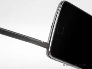
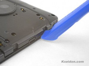
- Insert your fingernail or the flat end of a spudger into the notch on the bottom edge of the phone near the charging port.
- Pry with your fingernail or twist the spudger to release the back cover from the phone.
Step 2
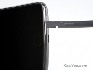
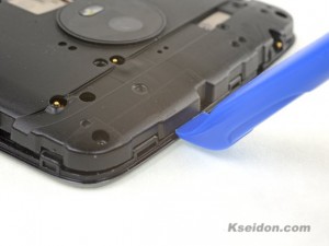
- Insert the flat end of a spudger into the seam and slide it along the bottom edge to release the clips holding the back cover to the phone.
Step 3
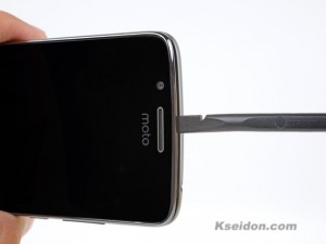
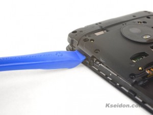
- Continue sliding the flat end of the spudger along the seam for the remaining sides of the phone.
Step 4
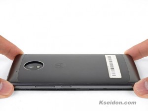
- Lift the back cover and remove it from the Moto G5.
- To reinstall the back cover, align the cover with the phone and squeeze along the edges to snap the clips back into place.
Step 5 Battery
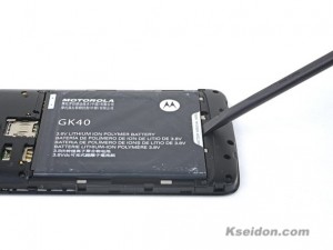
- Insert your fingernail or the flat end of the spudger into the notch below the battery.
- Pry with your fingernail or spudger until you free the battery from its recess.
Step 6 Remove the battery
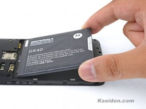
- When installing the battery, make sure the battery’s contacts line up with the three gold pins on the top right.
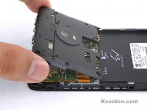
Step 7 LCD Screen and digitizer Assembly
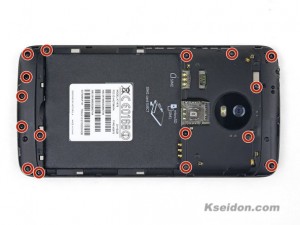
- Remove the sixteen 3 mm Phillips screws securing the motherboard and daughterboard covers.
Step 8
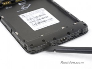
- Insert the flat end of a spudger into the seam below the daughterboard cover.
- Twist the spudger slightly to free the daughterboard cover.
- Remove the daughterboard cover.
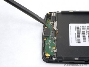
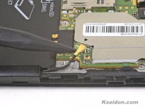
Step 9
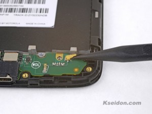
- Use the point of a spudger to pry up and disconnect the antenna cable from the daughterboard.
Step 10
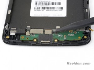
- Use the point of a spudger to pry up and disconnect the two flex cable connectors from the daughterboard.
Step 11
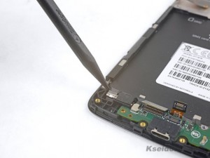
- Use the point of a spudger to pry up and loosen the vibration motor from its recess.
- The vibration motor can remain attached to the daughterboard.
Step 12
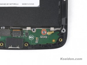
- Remove the 3.4 mm Phillips screw securing the daughterboard to the frame.
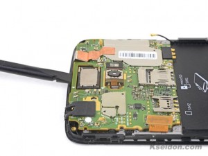
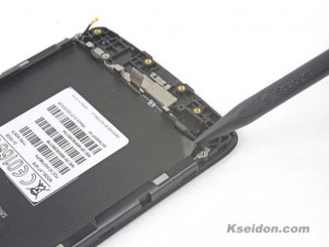
Step 13
- Insert the flat end of a spudger below the daughterboard, near the charging port.
- Pry the daughterboard up slightly with the spudger to loosen it from its recess.
- Lift and remove the daughterboard, taking care not to snare any cables.
Step 14
- Insert an opening tool into the seam on the right side of the phone near the top.
- Gently pry upwards until the hidden clip on the motherboard cover releases.
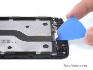
Step 15
- Insert an opening tool into the seam on the top of the Motorola G5, to the right of the indent.
- Gently pry upwards until the hidden clip on the motherboard cover releases.
-
Insert an opening tool in the seam on the left edge of the Moto G5, near the top.
-
Gently pry upwards until the hidden clip on the motherboard cover releases.
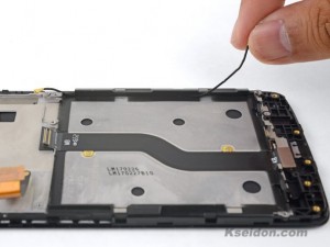
Step 17
- Make sure the three clips on the motherboard cover have not re-engaged.
- Lift up and remove the motherboard cover.
Step 18
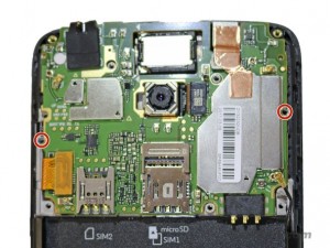
- Remove the two 4 mm Phillips screws securing the motherboard.
-
Use the point of a spudger to pry up and loosen the front facing camera module from its recess.
-
The camera module can remain connected to the motherboard.
- Use the point of a spudger to pry up and disconnect the display connector from the motherboard.
Step 21
- Take note of which motherboard socket the antenna cable is attached to. The triangle cutout on the motherboard shield points to the correct socket.
- Use the point of a spudger to pry up and disconnect the antenna cable from the motherboard.
- Be sure to attach the antenna cable to the same socket during reinstallation.
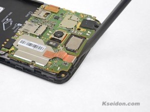
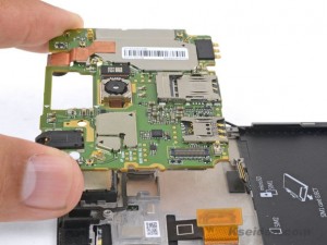
-
Insert the flat end of a spudger underneath the motherboard, near the top edge of the Moto G5.
-
Twist the spudger slightly to loosen the motherboard from the frame.Swing the top edge of the motherboard upwards, making sure it does not snag any cables.Do not remove the motherboard yet. It is still connected by a flex cable.
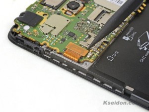
-
While supporting the motherboard at an angle, use the point of a spudger to pry out and disconnect the flex cable connector underneath the motherboard.
-
To reattach the connector, support the motherboard at a slight angle and line up the connector. Press the connector against the socket gently with your finger until it seats fully.
-
Lift up and remove the motherboard.
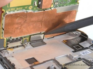
-
Use the point of a spudger to pry up a corner of the black battery mat.
-
Use your fingers to peel the battery mat from the frame.
- Use your fingers to lift and de-route the antenna cable from the right edge of the Moto G5.
- Be sure to re-route the antenna cable back onto the right edge of the phone before you replace the battery mat. The mat has a lip which holds the antenna cable in.
-
Insert an opening pick under the daughterboard flex cable.Slide the pick along the underside of the cable, releasing it from the frame.Remove the daughterboard flex cable.
Step 28
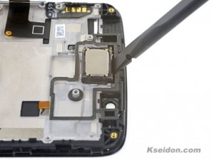
- Use the flat end of a spudger to pry up and loosen the earpiece module from its recess.
- Remove the earpiece module.
- During re-installation, be sure to check the orientation of the earpiece module and reinstall it the same way.
-
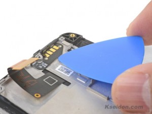
Insert an opening pick underneath the button contact flex cable.
-
Slide the opening pick to loosen the button contact flex cable from the frame.
-
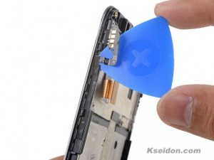
Insert an opening pick between the button assembly and the frame.
-
Gently slide the pick to release the button assembly from the frame.
-
Remove the button assembly.
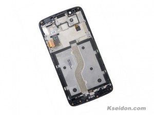
- Only the LCD screen and digitizer assembly (with frame) remains.
- Compare your new replacement part to the original part. You may need to transfer remaining components or remove adhesive backings from the new part before installing.
Post time: Jan-06-2021